GF-MAXCC Programmable Central Control System Interface Introduction and Function Introduction
2024-12-02
-
Interface Introduction
-
Physical Interface:
-
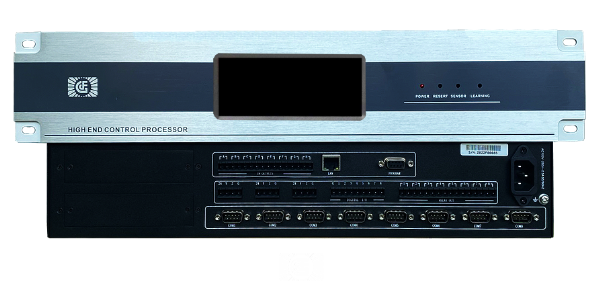
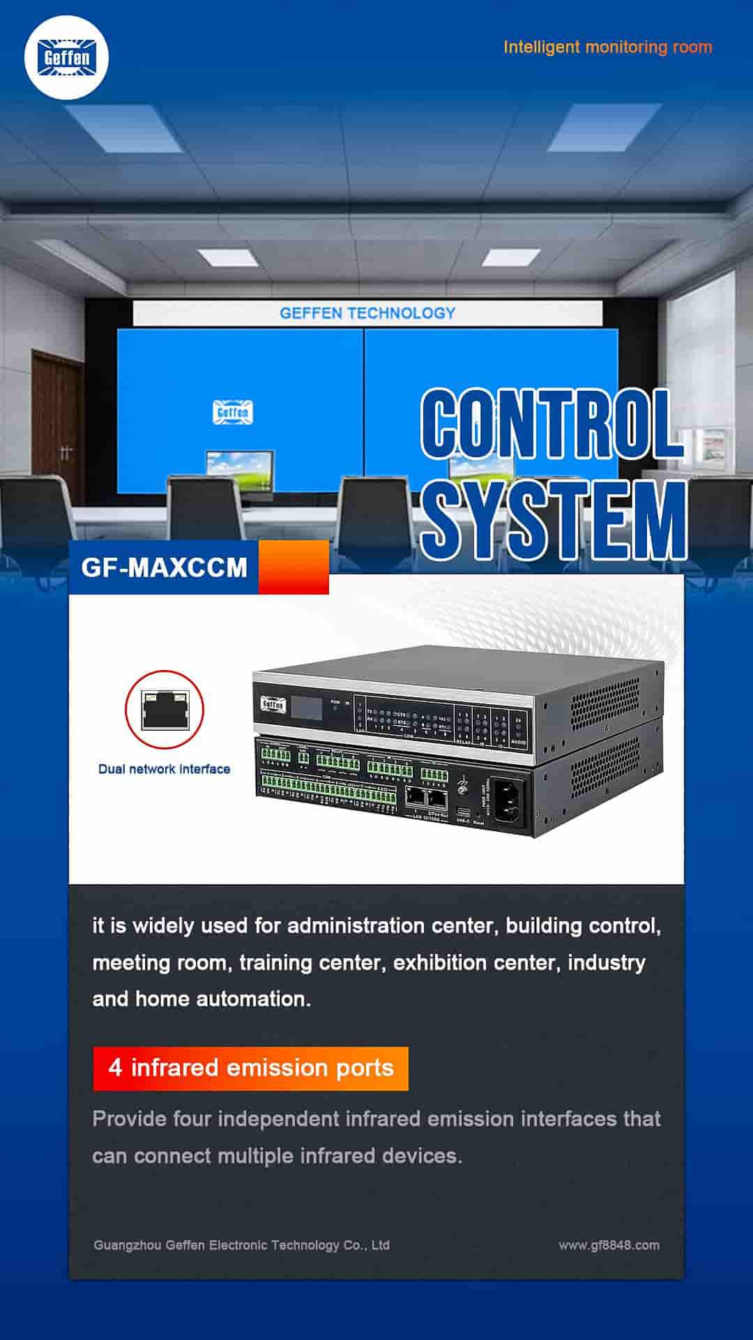
The GF - MAXCC Programmable Central Control System usually has a variety of physical interfaces. It may include Ethernet ports for network connectivity. These Ethernet ports allow the system to communicate with other network - enabled devices such as IP - based cameras, access control systems that support network protocols, and other smart building management devices. The data transfer speed of Ethernet ports can vary, commonly supporting 10/100/1000Mbps speeds depending on the model and configuration.
-
Serial ports (such as RS - 232, RS - 485) are also often present. RS - 232 is a standard serial communication interface. It is typically used to connect to devices like legacy audiovisual equipment, such as some older projectors that only support RS - 232 control. The RS - 232 interface has a relatively short communication distance, usually limited to about 15 meters. RS - 485, on the other hand, is designed for longer - distance communication and can support multi - drop configurations. It can be used to connect to a series of sensors or actuators that are distributed over a larger area, like in a factory automation environment or a large - scale building automation setup.
-
There may also be USB ports. USB ports can be used to connect external storage devices for system backup and recovery purposes. For example, an administrator can use a USB flash drive to store and transfer configuration files of the central control system. They can also be used to connect some USB - based input devices like keyboards and mice for local configuration and debugging of the system.
-
User Interface:
-
The software - based user interface of the GF - MAXCC system is likely to be designed with a graphical user interface (GUI). The GUI provides an intuitive way for operators to interact with the system. It usually has a main dashboard that displays the overall status of the connected devices and systems. For example, it can show the status of lights (on/off), the temperature readings of the HVAC (Heating, Ventilation, and Air - Conditioning) system, and the connection status of security cameras.
-
There are likely to be menus and sub - menus for different functions. For instance, a “Device Management” menu that allows users to add, delete, or configure connected devices. In this menu, for a connected smart light bulb, users can set parameters such as brightness, color temperature, and scheduling. There may also be a “Scenarios” menu where users can define and trigger different automation scenarios. For example, a “Meeting Mode” scenario can be defined to turn on the projector, lower the blinds, and adjust the lighting to an appropriate level.
-
Function Introduction
-
Device Control:
-
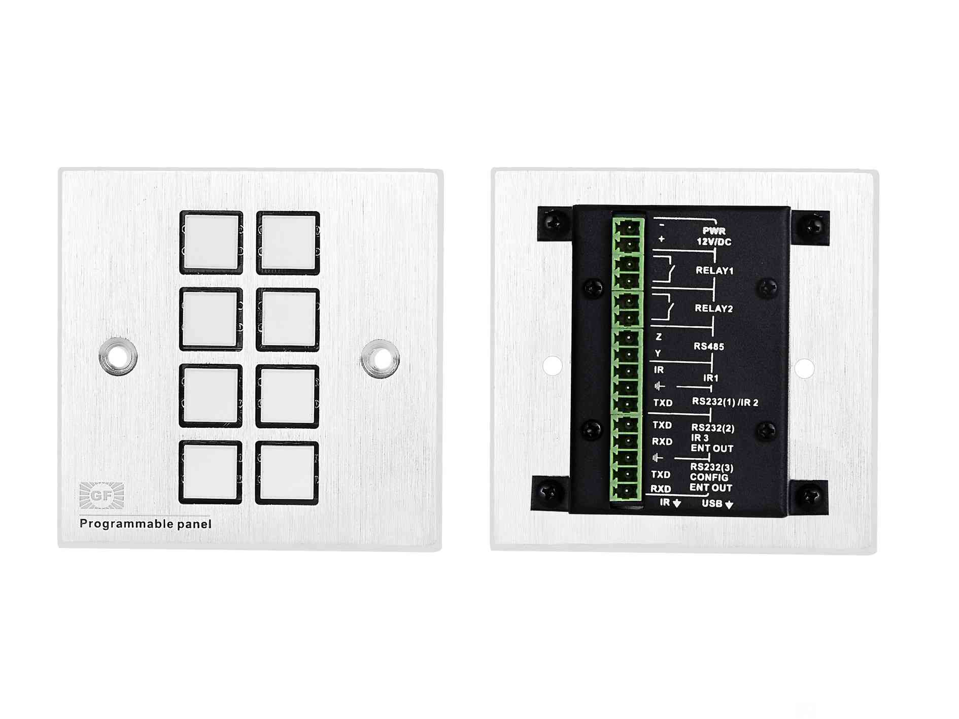
The GF - MAXCC Programmable Central Control System can control a wide range of devices. It can manage audiovisual equipment such as projectors, audio systems, and video conferencing equipment. For example, it can power on/off a projector, switch the input source of an audio amplifier, and start/stop a video conferencing session. In an office meeting room, when a user presses a “Meeting Start” button on the control panel, the central control system can send commands to turn on the projector, set it to the correct input for the laptop connection, and adjust the volume of the speakers to an appropriate level.
-
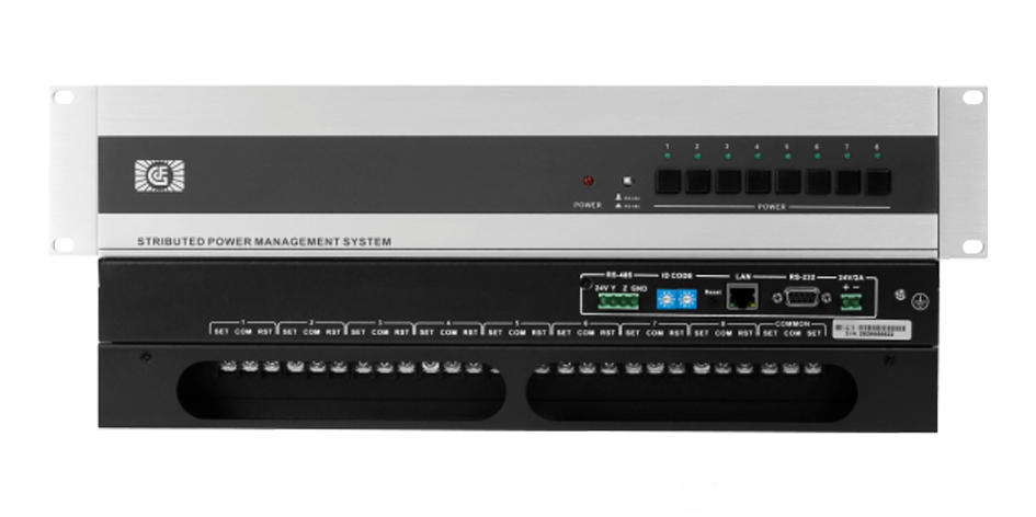
It is also capable of controlling building automation devices. This includes lighting systems, where it can adjust the brightness and color of individual lights or groups of lights. In a smart home environment, the system can dim the lights in the living room to a cozy level in the evening. It can also control the HVAC system, adjusting the temperature, humidity, and ventilation settings according to predefined schedules or user - initiated commands. For example, in a commercial building, the system can increase the cooling during peak business hours and reduce it during off - peak times to save energy.
-
Automation and Scenario Programming:
-
One of the key functions is the ability to create and execute automation scenarios. Users can define a sequence of actions for different situations. For example, a “Good Morning” scenario can be programmed to gradually increase the light intensity in the bedroom, open the curtains, and play soft music as an alarm clock alternative. These scenarios can be triggered by time - based schedules, such as running a “Work Mode” scenario at 9:00 am every weekday to turn on office equipment and adjust the lighting and temperature to the working environment settings.
-
They can also be triggered by events. For example, when a motion sensor detects movement in a certain area, the central control system can trigger a “Security Alert” scenario, which may include turning on security lights, sending an alert to a security console, and activating surveillance cameras in the area.
-
Monitoring and Data Logging:
-
The system can monitor the status of connected devices in real - time. It can continuously track parameters such as the power consumption of electrical equipment, the temperature and humidity levels of different rooms, and the usage time of various devices. For a data center, the central control system can monitor the temperature of servers and the power usage of the entire data center infrastructure.
-
Data logging is another important function. The system stores historical data about device operations and environmental conditions. This data can be used for analysis, such as identifying energy - consuming devices for energy - saving optimization, or analyzing the usage patterns of equipment to predict maintenance needs. For example, if the system records that a particular projector's usage time has reached a certain threshold, it can send a maintenance reminder to the administrator.
-
 :Building 3, Baizhong Creative Park, No. 240 Shilian Road, Panyu District, Guangzhou,Guangdong,China
 :+86 13928186280(Same WeChat/Whatsapp account)
 :+86 20-34702140